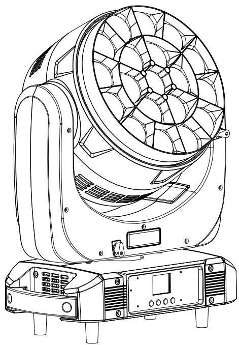
Model LU1940
Edition EN · 07 / 2026 · V2
Doc. No. LU1940-EN-02
19×40 W RGBW LED Matrix Beam · Bee-Eye
LU1940
Moving-head LED matrix fixture with 19 individually controllable RGBW pixels, pan/tilt and motorized zoom 3.5° – 50°
Operating manual. Please read completely before first use and keep for future reference.
Light Source
19 × 40 W4in1 RGBW LED
Pan / Tilt
540° / 270°8 / 16 bit
DMX Channels
21 – 997 channel modes
Zoom
3.5° – 50°motorized
Luminus Lighttech LU1940Foreword · About This Document
Foreword
00Welcome
Thank you for choosing the Luminus Lighttech LU1940 — a moving-head LED matrix fixture with 19 individually controllable 4-in-1 RGBW pixels, motorized zoom, and pan/tilt movement for stage, club and event use.
This document describes setup, operation, care and troubleshooting of the unit. Read the manual — particularly the Safety Instructions chapter — completely before first use, and keep it together with the unit. If the unit is passed on to a third party, this manual must be included.
0.1Symbol Key
Warning
Marks situations that may cause personal injury or damage to the unit. These instructions must be strictly followed.
Note
Marks useful supplementary information, tips or explanations that make the manual easier to understand.
Danger — Voltage
Marks situations posing a risk to life from electric current. Work on live parts must be performed exclusively by qualified personnel.
0.2Intended Use
The LU1940 is a professional lighting fixture for indoor use on stages, in clubs, and at events. Any other use — in particular outdoors or in humid environments (IP20) — is considered improper use and voids the warranty.
0.3Scope of Delivery
After unpacking, check the package contents for completeness and transport damage.
1 × Luminus Lighttech LU1940 LED matrix beam
1 × Mounting bracket with fixing screws
1 × Seetronic True power cable (1.5 m)
1 × Operating manual
Luminus Lighttech LU1940Contents · Overview
Table of Contents
—Overview
01Safety Instructions04
1.1General Safety04
1.2Installation and Mounting05
02Technical Specifications06
2.1Dimensions07
2.2Photometric Data08
03Controls09
3.1Display and Buttons09
3.2XLR Pin Assignment10
04Setup11
05Menu Navigation12
06Standalone Operating Modes13
07DMX Control14
7.1Reference Tables14
7.2Base Mode 21 CH15
7.3Base Mode 23 CH16
7.4Base Mode 35 CH17
7.5Pixel-Matrix Modes 78 / 92 / 97 / 99 CH18
08Troubleshooting19
09Cleaning & Maintenance20
—Quick Reference Card21
—Index22
Luminus Lighttech LU194001 · Safety Instructions
Chapter 01
01Safety Instructions
Read this chapter completely before first use. Damage resulting from failure to observe these instructions is excluded from the warranty.
1.1General Safety
Danger to life from electric current
Before any work on the unit, disconnect the mains supply on all poles and secure it against being switched back on. Before connecting, make sure that voltage and frequency of the mains supply match the rating label (AC 100 – 240 V, 50 / 60 Hz).
The protective earth conductor (yellow / green) must be properly grounded to avoid electric shock.
The unit is for indoor use only in a dry location — protection rating IP20. Never expose to rain, splashing water, or high humidity.
Install the unit in a well-ventilated location. Keep a minimum distance of ≥ 50 cm from adjacent surfaces and do not block any ventilation slots.
Maximum ambient temperature: ≤ 40 °C. The housing surface may reach up to 85 °C during operation — do not touch the housing with bare hands while operating.
Keep flammable materials (curtains, decorations) away from the unit — fire hazard.
Use a safety cable when installing the fixture. Never handle the unit by the head only — always hold it by the base.
Use only a straight, undamaged power cable. Never pull directly on the cable.
Do not touch any live wiring during operation — risk of electric shock.
Before Opening
Do not open the housing within 5 minutes after switching off, and let the unit cool down completely (approx. 15 minutes). Housing, lenses or the UV filter must be replaced if visibly damaged. There are no user-serviceable parts inside — in case of malfunction, stop operation and contact your dealer. Never attempt to repair the unit yourself.
Luminus Lighttech LU194001 · Safety Instructions
1.2Installation and Mounting
The LU1940 is mounted via the bracket at the base of the unit to a truss or floor stand. Installation must be performed by qualified personnel, out of the reach of people, and not above traffic routes.
Fall Hazard
The supporting structure must be able to safely bear at least 10 times the weight of the unit. Additionally secure the unit with a safety cable rated for at least 12 times the weight of the unit.
Mount the unit firmly enough that it cannot vibrate or slip during operation.
Check all screw and clamp connections for a secure fit before every use.
Ensure sufficient ventilation — minimum clearance ≥ 50 cm on all sides, so pan/tilt movement and cooling are not obstructed.
When aiming the fixture, allow for the full pan/tilt travel range (540°/360° · 270°) — adjacent structures or cables must not obstruct movement.
Note
Handle the unit only by its base during transport and installation — never by the head. The head contains the moving pan/tilt mechanics and may otherwise be damaged.
Before Switching On
Visually inspect for transport damage, loose screws and damage to the power cable.
Set the DMX address and channel mode on the display (see chapters 4 and 5).
Connect to mains power — the display lights up once the unit is correctly powered.
Pixel Effects
Each of the 19 LED cells can be controlled individually — the LU1940 can therefore display arrows, digits, letters and running effects directly in the matrix (see chapter 7.5).
All measurements in millimetres. Head diameter Ø 280 mm, overall height 420.5 mm in home position.
Fig. 2.1 — Front and side view. Left: width 376 · height 420.5 (head 382.5 / right side 403.5) · base width 372 · base height 115. Right: head diameter Ø 280 · neck 108 · base depth 210.
2.1.1Clearance for Movement
When mounting, allow for the fixture's full range of motion (pan 540°/360°, tilt 270°) as well as the motorized zoom and lens rotation mechanism. Adjacent truss parts, cables or other fixtures must not restrict movement.
Illuminance (lux) as a function of distance and zoom angle, measured per individual colour (R/G/B/W) and in additive 4-in-1 mixing. Values apply per individual LED cell.
Fig. 2.2 — Lux values and spot diameter at narrow zoom (3.5°) and wide zoom (50°) for distances of 1, 3, 5 and 8 m.
Note
The narrow zoom (3.5°) is suited to sharp beam effects over long throws, while the wide zoom (50°) is better for flood/wash effects at close range. At 50° zoom, the spot diameter at 5 m distance is already 4.46 m.
Luminus Lighttech LU194003 · Controls
Chapter 03
03Controls
3.1Display and Buttons
The control panel on the base of the unit features a 1.8″ TFT colour display (reversible 180°) and four buttons for menu navigation.
MENUOpens the programming menu / selects a menu function
DOWN (▼)Moves backward within the selected function / decreases the value
UP (▲)Moves forward within the selected function / increases the value
ENTERConfirms the selected function or the set value
Setting the DMX Address
Open the menuPress »MENU« until »Set DMX Address« appears, then confirm with »ENTER«.
Change the addressThe display shows »Set DMX Address · DMX Address: 001«. Adjust the value with »UP« and »DOWN«.
Save or discard»ENTER« saves the address and exits the menu. »MENU« exits without saving.
Luminus Lighttech LU194003 · Controls
3.2XLR Pin Assignment
The LU1940 uses both 3-pin and 5-pin XLR connectors for DMX-512. Use only shielded DMX cable (110 Ω) — not microphone cable.
Fig. 3.1 — 3-pin XLR male (DMX OUT)
Pin 1
Shield / GND
Pin 2
Data − (DATA −)
Pin 3
Data + (DATA +)
Fig. 3.2 — 5-pin XLR male (DMX OUT)
Pin 1
Shield / GND
Pin 2
Data − (DATA −)
Pin 3
Data + (DATA +)
Pin 4 / 5
Not assigned
Note
Fit a 120 Ω termination resistor at the last unit in the DMX chain to avoid signal reflections. The 3-pin and 5-pin connectors carry the same DMX signal — use one connector type consistently throughout a chain.
Luminus Lighttech LU194004 · Setup
Chapter 04
04Setup
Unpack and inspectCarefully remove the unit from its packaging and check for transport damage. Keep the packaging for transport or return shipping.
Choose a mounting locationWell-ventilated location with ≥ 50 cm clearance on all sides and free range of motion for pan/tilt.The mounting point must safely bear the weight of the fixture; the fixture must additionally be secured with a suitable safety cable of sufficient load rating in accordance with local regulations and laws.
Mount and secure the bracketAttach and lock the mounting bracket to the truss.Always use a suitable safety cable of sufficient load rating in accordance with local regulations and laws.
Connect the DMX cableConnect the controller's DMX output to DMX IN, and loop through DMX OUT to the next unit. Terminate the last unit with 120 Ω.
Connect the power cablePlug in and lock the Seetronic True power cable.
Set channel mode & DMX address»MENU« → »Channel« → select channel mode (21/23/35/78/92/97/99 CH), then »Set DMX Address« → set address (1 – 512) (see chapter 5).
Power onOnce power is applied, the unit automatically initializes pan/tilt/zoom and is then ready for operation.
4.1DMX Address Calculation
Depending on the channel mode, each unit occupies a fixed number of consecutive channels. The next unit starts at start address + channel count. Addresses for the first three units:
Channel Mode
Unit 1
Unit 2
Unit 3
21 CH
1
22
43
23 CH
1
24
47
35 CH
1
36
71
78 CH
1
79
157
92 CH
1
93
185
97 CH
1
98
195
99 CH
1
100
199
Luminus Lighttech LU194005 · Menu Navigation
Chapter 05
05Menu Navigation
Press »MENU« to open the programming menu. Use »UP«/»DOWN« to select an entry, and »ENTER« to confirm. »MENU« goes back one level.
In addition to control via a DMX controller, the LU1940 can also operate standalone. The operating mode is selected in the menu under »Mode«.
Mode
Description
DMX512
Standard operation — all channels are controlled by an external DMX controller (see chapter 7).
Master-Slave
Multiple units linked via DMX cable: the first unit (master) determines movement and colour, and every downstream unit in the same mode follows in sync — without needing its own DMX address.
Auto Run
The unit automatically plays back an internal light program without a controller or any user input.
Sound / Music
The unit reacts to music via its built-in microphone. Sensitivity is adjustable via »Mic Sense« (1 – 100).
Manual
Direct manual control of all channels via the menu, ideal for testing without a controller (see table below).
6.1Manual Control
In »Manual« mode, all functions can be set directly via the menu (password required, see »Adjust« in chapter 5):
Pan
0 – 255
Tilt
0 – 255
Focus (Zoom)
0 – 255
Rota (lens rotation)
0 – 255
Red / Green / Blue / White
each 0 – 255
Strobe
0 – 255
Luminus Lighttech LU194007 · DMX Control
Chapter 07
07DMX Control
The LU1940 offers seven DMX channel modes (21 – 99 CH). Many channels behave identically across all modes — these reference tables are used by cross-reference in chapters 7.2 – 7.5 to avoid repetition.
7.1Reference Tables
Ref. A — Colour Temperature / RGBW Mixing
0 – 15
No function (RGBW individual channels active)
16 – 175
8 intermediate steps of an R→G→B→W round mix
176 – 195
R100 % G100 % B100 % W100 % (full mix)
196 – 255
12 fixed colour temperatures, 2800 K – 8000 K
Ref. B — Macro Colours
0 – 9
No function
10 – 255
25 macro colours, 10 values each (colour n = CH value 10+(n−1)×10 … 19+(n−1)×10)
Same as the 21-CH mode (CH 1 – 21), extended with differentiated foreground/background pattern effects.
CH
Function
Description
01–08
Red / Green / Blue / White (+ Fine)
Same as CH 1 – 8 in the 21-CH mode
09
Colour Temperature
See Reference Table A
10
Macro Colour
See Reference Table B
11
Strobe
See Reference Table C
12–13
Dimmer (+ Fine)
Same as CH 12 – 13 in the 21-CH mode
14–17
Pan / Tilt (+ Fine)
Same as CH 14 – 17 in the 21-CH mode
18
Dimming Mode
See Reference Table D
19
Reset
See Reference Table E
20–21
Zoom / Lens Rotation
See Reference Table F
22
Pattern Rotation
Dynamic running pattern, see Reference Table G
23
Pattern Effect Speed
0 – 9 off · 10 – 132 forward · 133 – 255 reverse
24
Pattern Effect Fade
Crossfade time between patterns, 0 – 255
25–28
Pattern Background R/G/B/W
Colour behind the pattern, each 0 – 255
29
Pattern Dimmer
0 – 100 % pattern brightness
30
Background Dimmer
0 – 100 % background brightness
31
Pattern Change
Controls pattern switching, 0 – 255
32
Pattern Movement
Pattern movement (with CH 22), 0 – 255
33
Foreground Strobe
0 – 255
34
Background Strobe
0 – 255
35
Background Pattern Selection
0 – 255
Luminus Lighttech LU194007 · DMX Control
7.5Pixel-Matrix Modes (78 / 92 / 97 / 99 CH)
Each of these four modes corresponds to a base mode, extended with individual channels for each of the 19 LED cells — enabling arrows, digits, letters and running effects to be displayed pixel-precisely across the matrix.
Mode
Structure
Per LED Cell
78 CH
21-CH base (CH 1 – 21) + 19 × RGB
3 channels: R, G, B
92 CH
35-CH base (CH 1 – 35) + 19 × RGB
3 channels: R, G, B
97 CH
21-CH base (CH 1 – 21) + 19 × RGBW
4 channels: R, G, B, W
99 CH
23-CH base (CH 1 – 23) + 19 × RGBW
4 channels: R, G, B, W
Per-LED Channel Formula
All base channels (colour mixing, dimmer, pan/tilt, zoom, patterns, …) behave exactly as in the corresponding base mode (chapters 7.2 – 7.4). Starting from the first pixel channel, LED numbering follows linearly:
Note
In the 78-/92-CH modes there is no W channel per LED (only R/G/B, 3 channels/LED) — the formula and order remain the same, only the channel count per LED and the base channel count change (see table above).
Luminus Lighttech LU194008 · Troubleshooting
Chapter 08
08Troubleshooting
Below are solutions to the most common problems. For other faults, contact your dealer or Luminus Lighttech service.
8.1Unit Does Not Respond — No Light, Fan Not Running
#
Check
1
Check the mains connection and main fuse.
2
Measure the mains voltage at the connector (AC 100 – 240 V).
3
Check the power/display LED on the unit.
8.2Unit Does Not Respond to DMX Controller
#
Check
1
The DMX LED should be on. If not, check XLR cables and connectors for a proper link.
2
If a channel doesn't respond, verify the DMX address and polarity.
3
For intermittent dropouts, check the pins on the connectors and on the PCB of this unit and the previous one.
4
Try another DMX controller to rule it out as the source of the fault.
5
Do not run DMX cables parallel to high-voltage cables — risk of interference.
8.3One Channel Is Not Working Properly
The related stepper motor may be damaged, or the motor cable to the PCB may be broken.
The motor's driver IC on the PCB may be faulty.
Repairs by Qualified Personnel Only
Never attempt to open or repair the unit yourself. Repairs by unqualified persons can lead to damage or malfunction and will void the warranty.